

How Sand Casting Works and Why You Almost Certainly Need a Pattern
Sand casting is one of the oldest and most versatile metal manufacturing processes, yet it is often misunderstood. At its core, the idea sounds straightforward: create a cavity in sand, pour in molten metal, let it cool, and remove the casting.
In reality, success depends far more on this question:
How will the foundry reliably create a sand mold that produces this part correctly and repeatedly?
That is where the pattern comes in.
For most sand castings, the pattern is the critical tooling used to form the mold cavity. It is rarely identical to the finished part. A proper foundry pattern must account for shrinkage, draft, parting lines, machining allowance, cores, core prints, mold handling, and the practical realities of how the foundry will actually produce the casting.
A good casting begins with good tooling.
What Is Sand Casting?
In sand casting, a foundry packs specially prepared sand around a pattern. The pattern creates the negative space, or cavity, that will eventually become the metal part. Once the sand is compacted and the mold is assembled, the pattern is removed, leaving a hollow impression. Molten metal is poured into that cavity. After the metal solidifies, the sand mold is broken away to reveal the casting.
This process works well, but only when the mold cavity itself can be created accurately and repeatably. In nearly all traditional sand casting, that requires a pattern.
Why You Almost Certainly Need a Pattern
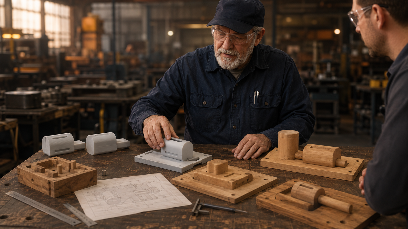
A pattern is physical tooling made from wood, plastic, metal, urethane, 3D printed material, or combinations of materials. It is specifically designed to shape the sand mold. It is engineered for the casting process, not just the final geometry.
A finished CAD model of the part often includes square corners, vertical walls, deep pockets, thin ribs, or tight internal features that look perfect on screen but cannot be molded cleanly. A proper foundry pattern must address:
- how the pattern will be withdrawn from the sand
- where the mold will separate, also called the parting line
- shrinkage compensation
- machining stock
- core placement and core prints
- mold handling and stability
- expected production volume and tooling life
Depending on the foundry process, the tooling strategy may also need to consider how molten metal enters the mold and how the casting is fed as it solidifies.
This is why simply sending a finished-part CAD model is rarely enough. It is only the starting point.
Freeze the Design Before Building the Pattern
Pattern construction should begin only after the design is as stable as possible. Once a patternmaker incorporates shrink factors, draft, machining allowance, parting strategy, core prints, and other foundry-specific adjustments, the pattern becomes dedicated manufacturing tooling.
Late design changes after this stage are expensive. A seemingly minor modification can require altering the parting line, adjusting draft angles, revising cores, rebuilding pattern sections, and re-validating everything.
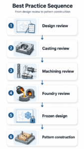
Best practice sequence:
Design review → casting review → machining review → foundry review → frozen design → pattern construction
A well-frozen design prevents paying twice: once to build the pattern, and again to revise it.
Draft: Why Straight Walls Cause Problems
Draft is a slight taper added to vertical surfaces so the pattern can be withdrawn cleanly from the sand without tearing or damaging the mold. Zero-draft walls often cause drag, sand crumbling, or mold damage, especially on deeper features.
The deeper or taller the feature, the more critical generous draft becomes. Large castings and deep draws create more surface area contact with the sand, increasing the risk of problems. Draft directly affects mold quality, casting consistency, and downstream cleanup costs.
Parting Lines: How the Mold Comes Apart
Most sand molds are made in two or more sections. The upper section is called the cope, and the lower section is called the drag. The parting line is where these sections meet.
Choosing the right parting line is crucial. A poor choice can create undercuts, excessive flash, mold damage, or difficult pattern withdrawal. A smart parting line simplifies the pattern, reduces defects, and lowers costs. This decision is a key reason why a finished-part model alone is not sufficient tooling.
Shrinkage: Why Patterns Are Larger Than the Finished Part
All metals shrink as they cool and solidify. Patternmakers use alloy-specific shrinkage factors, often with shrink rules or scaling, so the final casting ends up the correct size after contraction.
Ignoring shrinkage can produce undersized castings that may be difficult or impossible to salvage. The pattern must be intentionally oversized to compensate.
Why Many Castings Have “Simple” Features
Sand casting excels at creating the general shape efficiently. However, it is rarely the best process for tight-tolerance holes, precision bores, flat sealing surfaces, or threaded features. These are typically added or refined during machining.
Reasons for this approach include:
- machining achieves tighter tolerances and better surface finishes
- critical features can be located more accurately
- simplified cast geometry reduces mold complexity and defects
- foundries and machine shops each focus on their strengths
A rough casting fresh from the foundry is often intentional.
Machining Allowance: Extra Metal on Purpose
Machining allowance is the extra stock intentionally left on surfaces that will be machined later. It allows the machine shop to clean up surface texture, remove minor defects, and reach final dimensions reliably.
Too little allowance risks scrap. Too much allowance wastes material and machining time. Good pattern design strikes the right balance.
Sand Cores and Core Prints
Sand cores create internal cavities, passages, or hollow sections that cannot be formed by the external mold alone. Examples include water jackets in pump housings, valve bodies, and other parts with internal passages.
The core is placed in the mold before pouring. After casting, the sand is removed.
Core prints are locators built into the pattern that create seats in the mold for the cores. They help keep the core accurately positioned during pouring. Core prints are tooling features first. They are designed to support and locate the core, not to define the functional geometry of the finished part.
Core Boxes and Follow Blocks
Cored castings require additional tooling. Core boxes are used to form the sand cores themselves.
Follow blocks are shaped supports used when the pattern has irregular, curved, or unstable geometry that does not sit well in the flask. They support difficult areas during ramming so the mold can be made cleanly.
Unlike cores, follow blocks support external geometry during mold-making and do not create internal features in the final part.
Sand Printing: A Powerful Exception for Prototypes
Modern 3D sand printing can produce molds and cores directly from digital files, often eliminating the need for a traditional pattern for prototypes or complex one-offs. This can dramatically shorten lead time for design validation.
However, sand printing is usually more expensive per part. It shines for low quantities or highly complex internals, but traditional patterns remain more economical for repeat production.
Pattern Economics: Upfront Cost, Long-Term Value
A pattern is an upfront investment. While it can seem costly for a single part, the expense is amortized over the total number of castings produced. Higher volumes justify better and more durable tooling.
The more castings produced from a pattern, the less the tooling cost matters on a per-part basis. This is why production casting projects often justify more robust tooling than one-off prototype work.
Patterns Don’t Last Forever
Patterns wear from repeated use, sand abrasion, handling, and environmental exposure. Maintenance, including repairs, refinishing, and coatings, is normal. Eventually, many patterns need significant rework or full replacement, especially older wood patterns or high-volume tooling.
A worn or damaged pattern can create repeated casting problems. At some point, repairing the pattern between runs may become less efficient than rebuilding or replacing the tooling.
The Pattern Is the Manufacturing Plan
A well-designed pattern is not just a shape. It embodies the manufacturing strategy. It defines:
- mold separation and draw direction
- shrinkage compensation
- machining stock locations
- core strategy
- expected process repeatability
The key takeaway for customers is simple:
The finished part geometry is not the same as a foundry pattern. The pattern is process-specific tooling.
Conclusion
Successful sand castings depend on proper tooling. A good pattern accounts for draft, shrinkage, parting lines, machining stock, cores, and real-world foundry practices. While sand printing offers an excellent shortcut for prototypes, traditional patterns remain the most cost-effective route for production.
At JaegerTech, we specialize in bridging digital designs, 3D scanning, additive manufacturing, and practical foundry tooling. Whether you need a new pattern, core box, follow block, or help converting a finished-part model into a complete, production-ready tooling system, our goal is the same: make your castings easier to produce, easier to machine, and more repeatable.
About the Author: jaegertechgroup.com
STAY IN THE LOOP
Subscribe to our free newsletter.
Leave A Comment
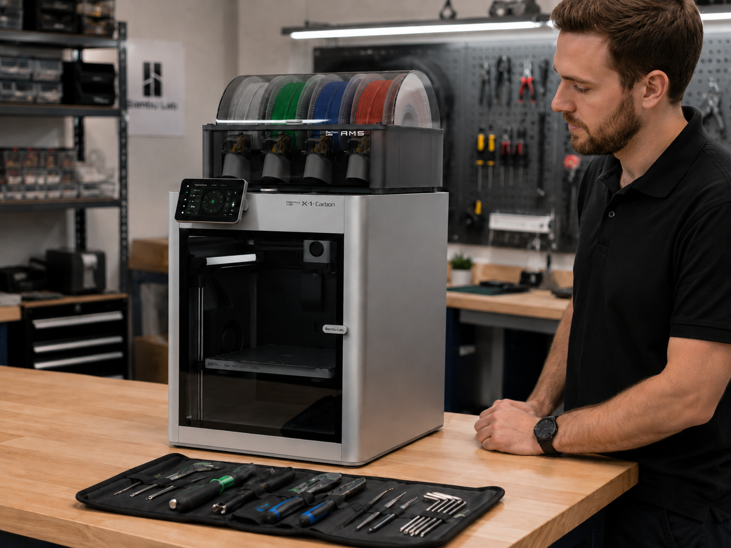
3D Printer Service and Repair for Bambu Lab, Prosumer, and Industrial Machines A 3D printer that is down, unreliable, clogged, poorly calibrated,

Why Domestic Tooling and Prototype Fabrication Still Matter Low-cost overseas tooling can be tempting. When a quote comes in dramatically cheaper than
Types of Sand Casting Patterns and When They Are Used In sand casting, the pattern is the tooling used to create the
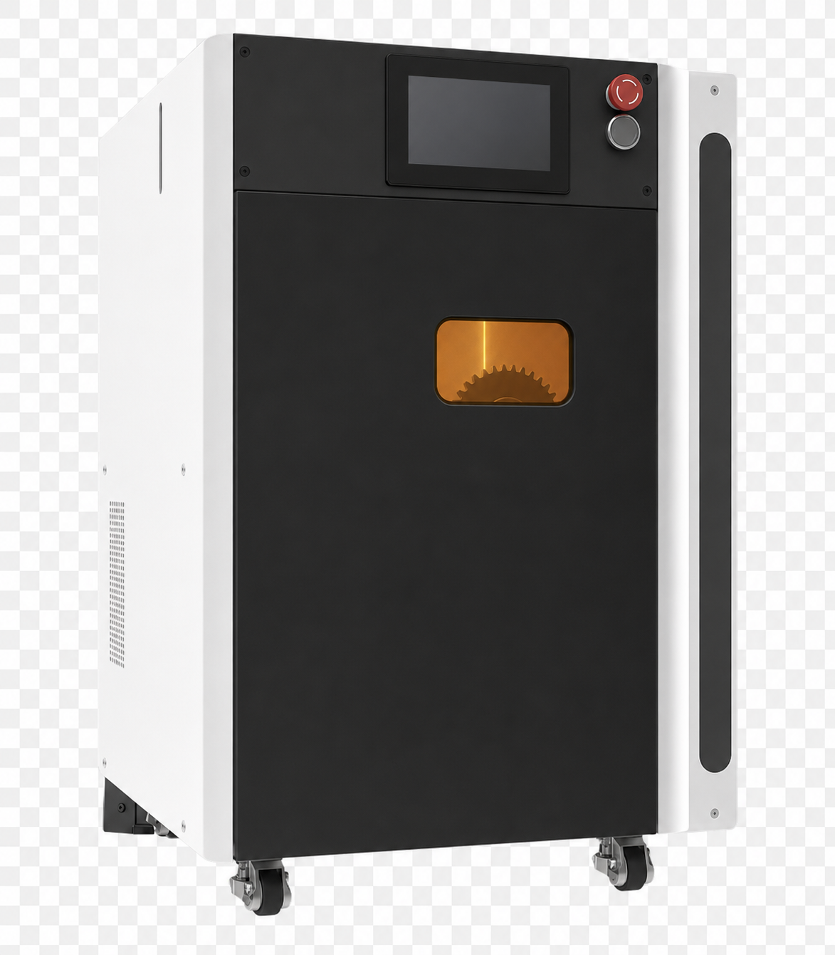
JaegerTech is preparing to add a compact selective laser sintering system for functional nylon and TPU parts to their lineup. The new