

Introducing the JaegerTech JT-SLM-130 Metal Additive Manufacturing Cell
Compact Metal Laser Powder Bed Fusion for Education, Research, and Precision Development
Metal additive manufacturing is often presented as a single-machine purchase: install a printer, load metal powder, and begin producing parts. In practice, a useful metal additive manufacturing laboratory requires more than the printer itself.
A functioning laser powder bed fusion workflow may involve inert atmosphere control, powder storage, powder screening, controlled cleanup, build-plate separation, support removal, surface finishing, inspection, operator training, and material-specific safety planning.
The JaegerTech JT-SLM-130 Metal Additive Manufacturing Cell is intended for universities, applied research laboratories, workforce development programs, and industrial development teams that want to establish compact metal additive manufacturing capability for smaller precision applications.
At the center of the system is the JT-SLM-130 Metal Additive Manufacturing System, a compact selective laser melting platform with a supplier-specified Ø130 mm × 80 mm build volume, 500 W water-cooled fiber laser, adjustable layer settings, controlled inert-atmosphere operation, and open-access process parameter management.
Rather than positioning the JT-SLM-130 as a stand-alone printer, JaegerTech is developing the offering as a configurable cell that may include powder screening, nitrogen generation, powder cleanup equipment, post-processing options, and implementation guidance appropriate to the customer’s intended application.
Why a Compact Metal AM Cell Makes Sense
Large production-class metal additive systems are necessary for some manufacturing environments, but they are not required for every educational, research, or development objective.
A university may want to teach students the fundamentals of laser powder bed fusion, build test coupons, and evaluate density, porosity, surface finish, or process parameters.
A research laboratory may need a compact system for experimental geometries, small test samples, lattice structures, thermal concepts, or material-development work.
An industrial development team may want to determine whether metal additive manufacturing is suitable for a small tooling component, prototype feature, fixture element, or specialized precision part before committing to a larger production investment.
The JT-SLM-130 is intended to address these smaller-format applications while giving qualified users access to the actual process variables and supporting workflow that make metal additive manufacturing meaningful.
JT-SLM-130 Metal Additive Manufacturing System
The JT-SLM-130 uses Selective Laser Melting, also commonly categorized as Laser Powder Bed Fusion, to produce metal components from powder-based feedstock.
During operation, a controlled layer of metal powder is spread across the build area. A focused fiber laser selectively melts the geometry for that layer. The machine repeats the deposition and melting process layer by layer until the component is complete.
This approach may support the production of smaller precision components, test coupons, research samples, internal passages, lattice structures, tooling features, prototype hardware, and other geometries suited to metal additive manufacturing.
Core Printer Features
| Feature | Supplier-Specified Detail |
|---|---|
| Build volume | Ø130 mm × 80 mm cylindrical build area |
| Laser system | 500 W water-cooled fiber laser |
| Laser spot size | 50–100 µm adjustable |
| Powder layer thickness | 20–120 µm adjustable |
| Scanning speed | ≤10 m/s |
| Forming speed | 5–20 cm³/h |
| Powder feeding method | Bottom feeding with unidirectional variable-speed powder spreading |
| Recoater blade | Flexible blade |
| Substrate fixing method | Quick-release magnetic type |
| Process atmosphere | Nitrogen or argon, depending on application requirements |
| Working oxygen content | ≤100 ppm, supplier-specified |
| Process parameter access | Open-access parameter management |
| Data formats | CLI, SLC, STL and other supported formats |
| Operating environment | Windows 10 or Windows 11 |
| Rated electrical power | 3 kW |
| Machine dimensions | 720 mm W × 653 mm D × 1726 mm H |
500 W Water-Cooled Fiber Laser
The JT-SLM-130 is specified with a 500 W water-cooled fiber laser. For universities and development laboratories, this configuration provides a platform for investigating the relationship between laser energy, scan strategy, layer thickness, support design, part geometry, atmosphere control, and resulting part characteristics.
Potential instructional or research investigations may include:
- Laser power and scan-speed relationships
- Layer thickness and surface finish
- Hatch and contour strategy
- Density and porosity studies
- Metallographic examination
- Build orientation and support strategy
- Mechanical coupon production
- Post-processing effects
- Application-specific parameter development
As with any metal additive manufacturing process, part quality and resulting material properties depend on powder quality, validated parameters, atmosphere control, support design, post-processing, and inspection.
Open Parameters for Research and Instruction
For education and applied research, the ability to study the process is often as important as producing the part.
The JT-SLM-130 is specified with open-access process parameter management, allowing appropriately trained users to evaluate controlled process changes rather than working exclusively from fixed production recipes.
This feature may be particularly useful for:
- Engineering and materials science coursework
- Research studies involving test coupons
- Design-of-experiments projects
- Surface and density evaluations
- Process optimization work
- Workforce development training
- Early-stage application development
Parameter changes should be documented and evaluated through appropriate testing or inspection before printed components are used in demanding applications.
A Configurable Metal Additive Manufacturing Cell
A metal powder bed fusion printer does not operate in isolation. Powder handling, process gas, cleanup, powder screening, post-processing, inspection, and workflow planning must be considered as part of the installation.
The JaegerTech cell concept is built around a compact metal printing platform with supporting modules selected according to the intended material and customer application.
Core Cell Components
| JaegerTech Component | Intended Function |
|---|---|
| JT-SLM-130 Metal Additive Manufacturing System | Produces smaller metal components through laser powder bed fusion |
| JT-PS-8400 Inert Powder Sieving System | Supports controlled screening of recovered powder for applicable material systems |
| JT-NG-001 Nitrogen Generation System | Provides nitrogen for compatible inert-atmosphere processes |
| JT-PV-001 Metal Powder Vacuum System | Supports controlled collection of powder and powder-derived residue when suitable for the selected material and facility requirements |
Additional equipment, procedures, and facility controls may be required depending on powder selection, operating environment, research purpose, and institutional requirements.
JT-PS-8400 Inert Powder Sieving System
The JT-PS-8400 Inert Powder Sieving System is intended to support controlled screening and recovery procedures for applicable metal powders.
The supplier specifies an inert operating environment and a combined ultrasonic and vibration-assisted sieving process. In an educational or research workflow, this system may help customers establish powder recovery procedures while teaching the importance of powder condition, contamination control, traceability, and material-specific validation.
Supplier-Specified Technical Data
| Specification | Value |
|---|---|
| Power supply | AC 220 V, 16 A, 50 Hz |
| Rated power | 350 W |
| Ultrasonic power | 100 W |
| Screening method | Ultrasonic plus vibration-assisted sieving |
| Screen diameter | Ø400 mm |
| Screen mesh | 200 mesh |
| Inert gas pressure | 0.5–0.7 MPa |
| Equipment dimensions | 850 × 805 × 2020 mm |
| Supplier-listed powder classes | Stainless steel, die steel, cobalt-chromium alloy powder, superalloy, etc. |
The supplied literature does not expressly identify this sieving system for titanium or aluminum powder handling. Those material applications require additional documentation and application review before being represented as supported by a configured cell.
JT-NG-001 Nitrogen Generation System
The JT-NG-001 Nitrogen Generation System is intended to provide a dedicated nitrogen source for operations where nitrogen is appropriate for the selected material and process.
The supplier specifies a nitrogen purity of 99.999% and a standard flow rate of 3 Nm³/h, with PLC-based controls and real-time digital purity monitoring.
Supplier-Specified Technical Data
| Specification | Value |
|---|---|
| Nitrogen purity | 99.999% |
| Standard flow rate | 3 Nm³/h |
| Controlled nitrogen pressure | 0.1–0.65 MPa |
| Maximum nitrogen pressure | 0.8 MPa |
| Nitrogen dew point | ≤ -40 °C |
| Nitrogen oil content | ≤0.002 ppm |
| Particulate content in nitrogen | ≤0.01 ppm |
| Power supply | AC 220 V, 50–60 Hz |
| Equipment power | 200 W |
| Dimensions | 1400 × 700 × 2100 mm |
| Required compressed-air inlet pressure | 0.6–0.8 MPa |
| Required compressed-air dew point | ≤ -10 °C |
| Controls | PLC-based manual / automatic operation |
| Purity monitoring | Real-time digital display |
The JT-NG-001 requires a suitable source of clean, dry compressed air. Nitrogen is not assumed to be appropriate for every powder or process objective. Argon or other process-gas arrangements may be required for certain applications.
JT-PV-001 Metal Powder Vacuum System
Metal powder cleanup must be treated as part of the operating workflow, not as an afterthought.
The JT-PV-001 Metal Powder Vacuum System is intended to support controlled collection of metal powder and powder-derived residue within an appropriately planned metal additive manufacturing environment.
The supplier identifies this unit as an explosion-protected vacuum cleaner and provides an explosion-protection designation in its technical literature. JaegerTech will review available supporting documentation and material suitability as part of system configuration and quotation.
Supplier-Specified Technical Data
| Specification | Value |
|---|---|
| Power supply | 220 V |
| Power | 1.75 kW |
| Airflow | 300 m³/h |
| Vacuum pressure | 2400 mm H₂O |
| Filter material | Antistatic / ESD polyester |
| Filtration rating | 1 µm |
| Filter cleaning method | Manual filter shaking |
| Collection method | Dust bucket |
| Collection capacity | 80 L |
| Air inlet diameter | 50 mm |
| Dimensions | 650 × 750 × 1500 mm |
| Supplier-listed explosion-protection designation | 1 1/3D Ex h IIC T160°C Da/Dc |
The JT-PV-001 is not represented as approved or suitable for every metal powder or every classified-location requirement. Reactive powder workflows, including titanium or aluminum powder applications, require additional documentation, compatibility review, facility evaluation, and suitable operating procedures.
Material Strategy: Begin With Stainless Steel
The supplier identifies the JT-SLM-130 printer for several general metal material classes:
| Material Class | Published Positioning |
|---|---|
| Stainless steel | Recommended starting material pathway for many educational and introductory research installations |
| Titanium alloy | Supplier-listed printer material class; requires application and safety review |
| Mold steel | Supplier-listed printer material class; requires application review |
| Cobalt-chromium alloy | Supplier-listed printer material class; requires application review |
| Aluminum alloy | Supplier-listed printer material class; requires additional powder-handling and safety review |
For most universities and introductory research programs, JaegerTech recommends beginning with an appropriate stainless steel powder system. Stainless steel provides an industrially relevant starting point for process studies, test coupons, dimensional evaluation, support removal, surface finishing, and instructional development without immediately expanding the cell into more demanding reactive-powder workflows.
The supplied literature does not provide sufficient confirmation for JaegerTech to publicly represent copper alloy capability as part of this offering.
Listed printer materials do not establish that every supporting component in the cell is validated or approved for every powder type.
Post-Processing and Laboratory Completion Modules
Printing a metal part is only one portion of the workflow. Once a build is complete and appropriate powder-removal procedures have been followed, the printed component may still need to be separated from the build plate, cleaned of remaining supports, surface finished, measured, and documented.
JaegerTech can help customers plan optional post-processing equipment and outside-service pathways according to their expected use.
Optional Post-Processing Components
| Optional Module | Intended Function |
|---|---|
| JT-BS-001 Build Plate Separation Bandsaw | Supports separation of selected fully depowdered stainless-steel parts and support structures from the build substrate |
| JT-MB-001 Enclosed Media Blasting Cabinet | Supports surface finishing of fully depowdered printed metal components following appropriate separation and support removal |
| JT-FT-001 Metal AM Finishing Tool Kit | Provides vise, dedicated hand tools, files, deburring equipment, and controlled local finishing tools |
| JT-IN-001 Basic Inspection Kit | Supports basic dimensional inspection using calipers, micrometers, and documented evaluation methods |
| Additional Build Plates | Supports continued laboratory operation while plates are inspected or resurfaced |
Some post-processing requirements may be better addressed through qualified outside providers during initial adoption.
Processes Commonly Evaluated Separately
| Capability | Initial Implementation Approach |
|---|---|
| Stress relief or heat treatment | Evaluate by material and application; outside provider may be practical initially |
| Precision build-plate separation | Outside wire EDM or machining service for sensitive parts |
| Build-plate resurfacing | Qualified grinding or machining service |
| Metallurgical testing | University laboratory capability or qualified outside testing provider |
| Reactive powder workflows | Separate review before implementation |
Recommended Workflow Separation
A compact printer does not mean that every supporting operation should occur in the same room.
A responsible metal additive manufacturing installation should consider separation between powder-handling activities, dirty post-processing operations, and clean inspection or teaching functions.
Recommended Functional Areas
| Work Area | Typical Operations | Planning Objective |
|---|---|---|
| Controlled Powder and Printing Area | Printer operation, powder loading, unloading, depowdering, powder storage, powder vacuum use, powder sieving | Control loose powder, contamination, operator access, and material handling |
| Separate Post-Processing Area | Bandsaw separation, support removal, rotary-tool finishing, enclosed media blasting | Keep cutting debris, finishing dust, abrasive residue, noise, and possible ignition sources away from loose powder handling |
| Clean Inspection and Teaching Area | Dimensional inspection, microscopy, documentation, finished-part review, design discussion | Protect inspection equipment and student-facing spaces from powder and finishing debris |
The appropriate final layout depends on the selected material, building configuration, institutional requirements, safety review, and intended operating workflow.
Facility Planning Considerations
The JT-SLM-130 printer has a compact footprint, but a complete metal additive manufacturing workflow requires additional space and infrastructure for supporting equipment, access clearances, process gas, powder management, post-processing, and inspection.
Initial Facility Planning Summary
| Planning Item | Current Supplier-Specified or Recommended Consideration |
|---|---|
| Printer electrical supply | 100–110 V or 220–240 V AC, 50/60 Hz, single phase, 16 A |
| Printer rated power | 3 kW |
| Printer footprint | 720 × 653 mm, plus required service clearance |
| Laser cooling | Water-cooled fiber laser; final cooling arrangement to be confirmed at configuration |
| Nitrogen generator electrical supply | AC 220 V, 50–60 Hz |
| Nitrogen generator compressed-air requirement | 0.6–0.8 MPa inlet pressure, ≤ -10 °C dew point |
| Powder sieve inert gas pressure | 0.5–0.7 MPa |
| Powder vacuum electrical supply | 220 V |
| Powder-handling area | Controlled access, grounding and bonding evaluation, PPE, storage, housekeeping, written procedures |
| Post-processing area | Separate work area recommended for cutting, finishing, and media blasting operations |
| Clean inspection area | Recommended for dimensional inspection, documentation, and student-facing evaluation |
A customer planning to add the JT-NG-001 nitrogen system should confirm that an appropriate clean, dry compressed-air supply is available or budget for the required compressor and air-treatment equipment.
Intended Users and Applications
Universities and Technical Education Programs
The JT-SLM-130 cell may provide a practical platform for instruction involving:
- Laser powder bed fusion fundamentals
- Design-for-additive manufacturing
- Materials science and metallurgy
- Powder handling and traceability
- Process-parameter studies
- Metallographic inspection
- Mechanical test coupon production
- Post-processing workflow development
- Advanced manufacturing workforce training
Applied Research Laboratories
Potential research uses may include:
- Small experimental metal geometries
- Density and porosity studies
- Surface engineering investigations
- Lattice and porous structures
- Thermal-management concepts
- Material and parameter studies
- Small functional research components
Industrial Development Teams
Potential industrial development uses may include:
- Prototype metal components
- Small tooling inserts
- Fixture elements
- Application feasibility studies
- Early-stage metal AM process evaluation
- Small precision development parts
The JT-SLM-130 is positioned as a compact educational, research, and development platform. It is not represented as a replacement for larger validated production systems.
Working With JaegerTech
JaegerTech’s role is not limited to delivering equipment. A metal additive manufacturing system must be matched to the customer’s application, facility, material strategy, post-processing requirements, and operational capabilities.
JaegerTech can assist customers with:
- Cell configuration planning
- Initial application review
- Educational and research use-case development
- Stainless-steel-first implementation planning
- Supporting equipment selection
- Powder-handling workflow considerations
- Post-processing strategy
- Facility layout planning
- Startup training coordination
- Future expansion review
For institutions entering metal additive manufacturing, the goal is not simply to own a metal printer. The goal is to establish a practical, appropriately planned workflow that supports useful instruction, credible research, and measured application development.
Request Information on the JT-SLM-130 Cell
The JaegerTech JT-SLM-130 Metal Additive Manufacturing Cell is intended for universities, research laboratories, workforce development programs, and industrial development teams seeking compact metal laser powder bed fusion capability for smaller precision applications.
Contact Jaeger Technology Group to discuss:
- Initial stainless-steel system configuration
- Educational or research objectives
- Supporting powder-handling equipment
- Facility planning considerations
- Optional post-processing modules
- Application review and quotation options
Specification and Application Notice
Technical specifications, equipment descriptions, listed material classes, performance values, filter-life values, oxygen-content values, gas-purity values, and explosion-protection designations presented in this article are based on current supplier-provided information and are subject to confirmation at quotation and before sale.
Listed printer material capabilities do not represent that a complete cell configuration is validated, certified, approved, or suitable for every listed powder, facility, classified hazardous location, regulatory requirement, or end-use application. Material suitability, process parameters, atmosphere requirements, ancillary equipment selection, powder-handling procedures, cleanup equipment, facility controls, resulting part properties, and safety requirements must be evaluated for the intended application.
Safety-related equipment descriptions, including supplier-listed explosion-protection designations, are provided for equipment-identification and configuration-review purposes only. They do not constitute a representation that the equipment or a complete installation is certified or approved for a particular powder, classified location, or regulatory standard unless separately confirmed in writing.
Metal additive manufacturing equipment and metal powders must be operated only by appropriately trained personnel using procedures suitable for the selected material and installation environment.
About the Author: jaegertechgroup.com
STAY IN THE LOOP
Subscribe to our free newsletter.
Leave A Comment
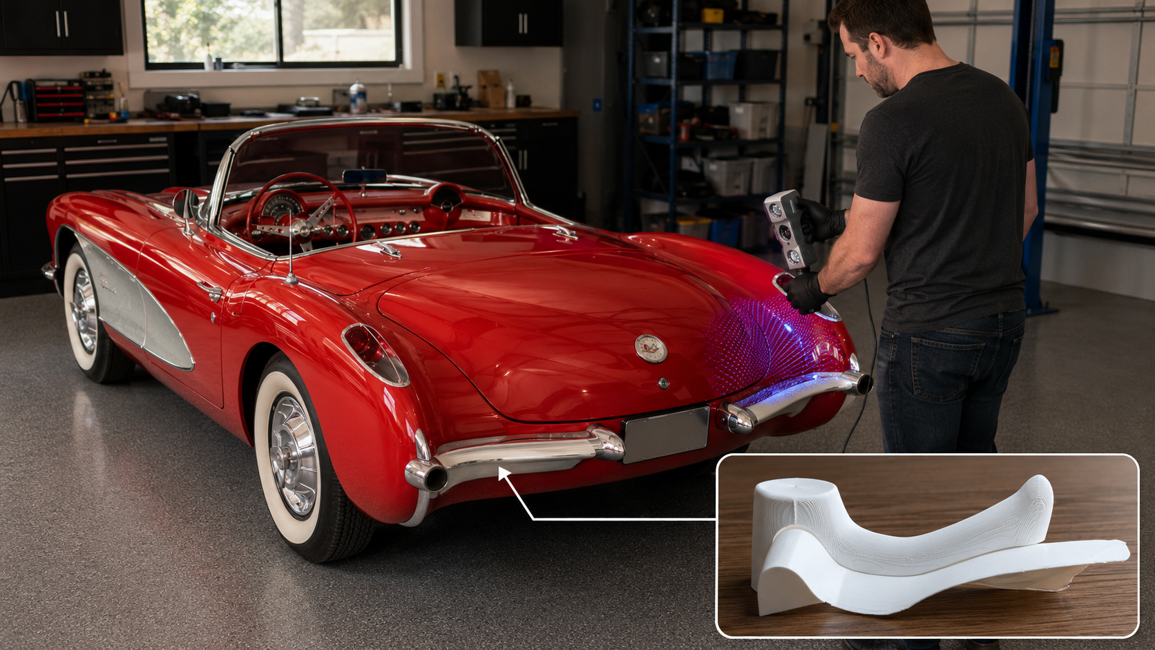
Best $150 I’ve Ever Spent on This Car Classic car projects have a way of turning simple problems into complicated ones. A
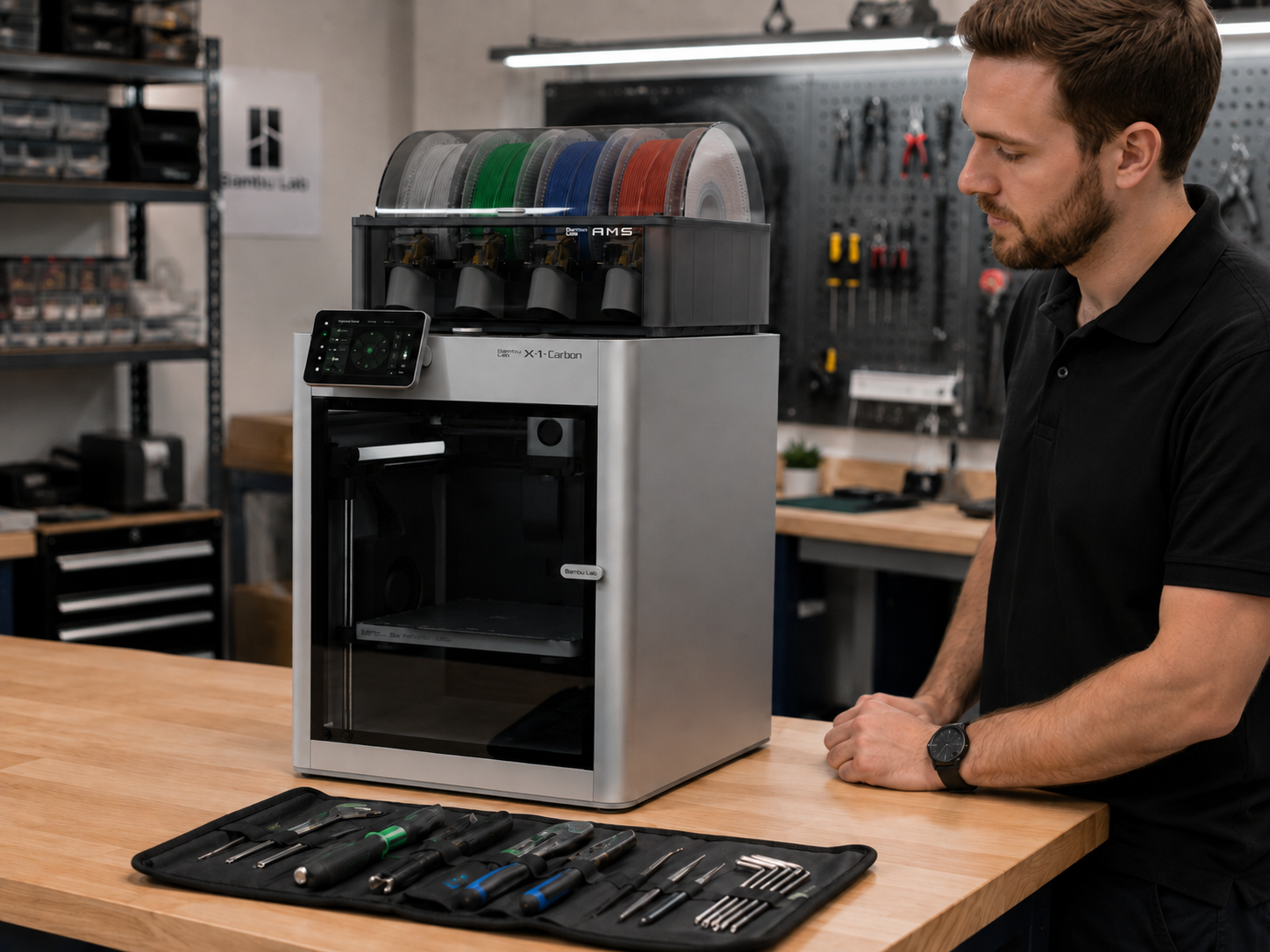
3D Printer Service and Repair for Bambu Lab, Prosumer, and Industrial Machines A 3D printer that is down, unreliable, clogged, poorly calibrated,
Why Domestic Tooling and Prototype Fabrication Still Matter Low-cost overseas tooling can be tempting. When a quote comes in dramatically cheaper than
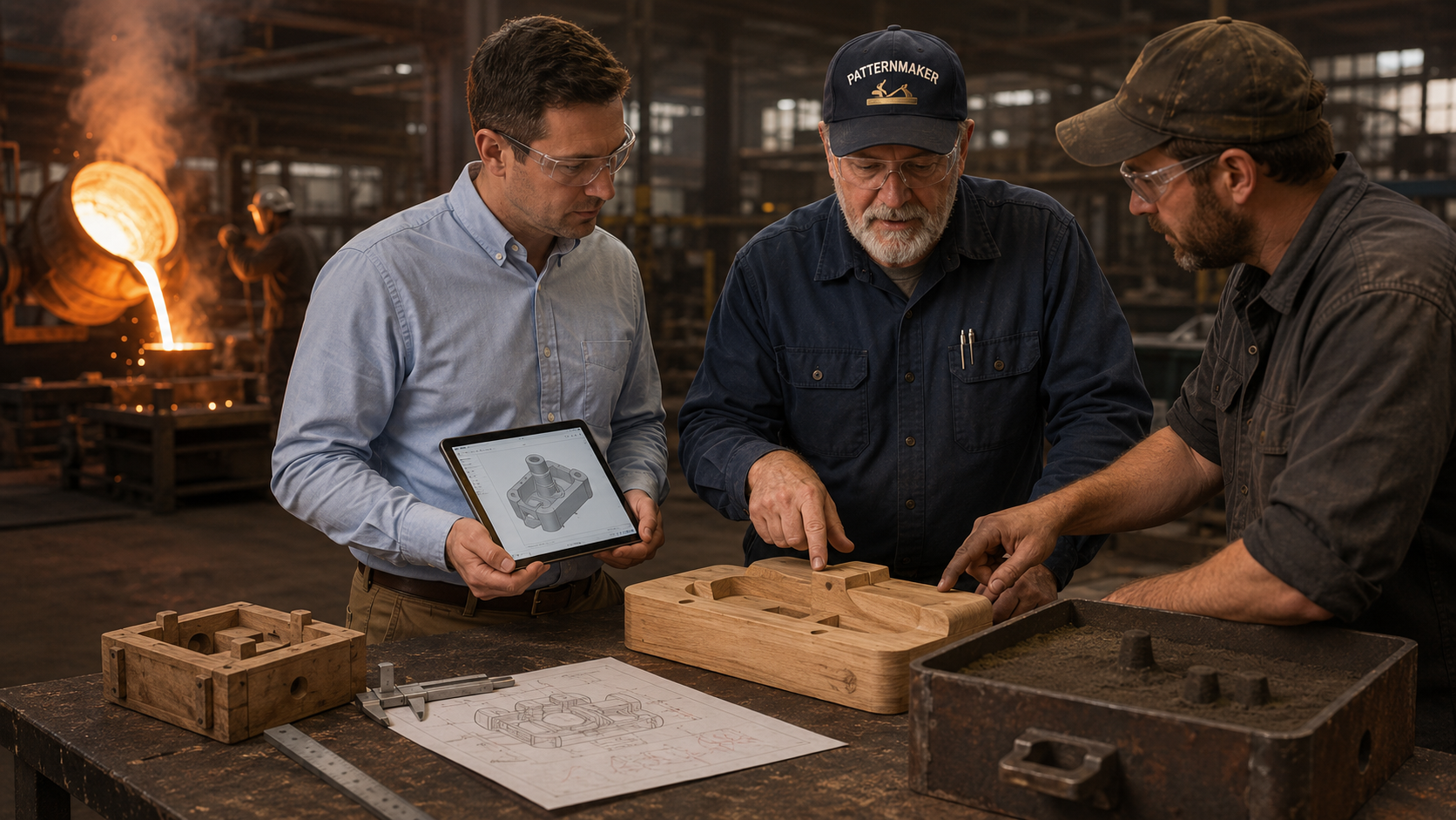
How Sand Casting Works and Why You Almost Certainly Need a Pattern Sand casting is one of the oldest and most versatile