
From MVP to Market: How Consumer Electronics Become Real Products
A working MVP is an important milestone.
It proves that the idea can function.
But there is a major difference between:
Idea → Working Prototype → Manufacturable Product → Market Launch
That middle transition is where most of the real product-development work happens.
A consumer electronic product may begin with a development board, battery, display, sensor, motor, driver, buttons, and a 3D-printed enclosure.
That can be enough to prove the concept.
But before that product can be manufactured and sold, the design has to become repeatable, serviceable, testable, safe, supportable, and financially practical.
At Jaeger Technology Group, we look at this transition as a complete engineering and commercialization process.
Step 1: Prove the Core Function
The MVP should answer the most important question first:
Does the idea actually work?
At this stage, the development path may look like:
Concept → Development Board → Temporary Wiring → 3D-Printed Enclosure → Functional MVP
The MVP does not need to be beautiful.
It needs to prove the critical functions.
Depending on the product, that might mean validating:
- Sensors
- Motors or actuators
- Displays
- User controls
- Wireless communication
- Battery life
- Charging
- Mechanical fit
- Basic ergonomics
- Thermal behavior
Speed and flexibility matter more than production optimization at this stage.
Step 2: Turn a Collection of Parts Into a System
Early prototypes frequently contain separate modules connected together with jumper wires, development boards, breakout boards, temporary terminal blocks, and external power supplies.
That is normal.
But production requires something more controlled.
The electronics need to evolve from:
Loose Modules → Defined Architecture → Integrated Electronics → Repeatable Assembly
That may involve:
- Custom wiring harnesses
- Standardized connectors
- Defined power distribution
- Fuses or resettable protection
- Voltage regulation
- Battery protection
- ESD protection
- Strain relief
- Mounting provisions
- Service access
The goal is to remove guesswork.
A production assembler should not have to remember which wire goes where.
Step 3: Decide Whether Development Boards Still Make Sense
Development boards are excellent for proving ideas.
They provide processors, communications, memory, power regulation, and I/O without requiring a custom circuit board on day one.
But as the product matures, the architecture should be reconsidered.
The progression often looks like:
Development Board → Carrier Board → Semi-Custom Electronics → Custom PCB
A custom or semi-custom board may provide:
- Smaller size
- Lower cost
- Better connector placement
- Fewer wires
- Improved reliability
- Easier assembly
- Better test access
- Cleaner packaging
That does not mean every product needs a custom PCB immediately.
For ten units, a development board may still make perfect sense.
For hundreds or thousands of units, the economics may change significantly.
Step 4: Mechanical and Electrical Design Must Develop Together
The enclosure is not simply a shell around the electronics.
It is part of the system.
A change in one area often affects several others:
Battery Size → Enclosure Size → Weight → Mounting → Manufacturing Cost
Or:
Display Change → New Bezel → New Wiring → New Assembly Process
Or:
Different Motor → Higher Current → Different Driver → Larger Battery → More Heat
That is why electrical and mechanical design should evolve together.
The enclosure may need to accommodate:
- Electronics
- Batteries
- Displays
- Sensors
- Motors
- Cameras
- Antennas
- Speakers
- Controls
- Connectors
- Cooling
- Cable routing
- Service access
A product that looks good in CAD but cannot be assembled or serviced efficiently is not finished.
Step 5: Define the Power Architecture
Power deserves early attention.
An MVP might run from a USB cable or bench power supply.
The production product may need:
Wall Power → Power Supply → Regulation → Battery/Charging → Product Electronics
Or:
Battery → Protection Circuit → Voltage Regulation → Controller → Loads
Questions may include:
- Battery or external power?
- USB-C charging?
- Battery fuel gauge?
- Sleep modes?
- Overcurrent protection?
- Thermal protection?
- Undervoltage cutoff?
- Charging indicator?
- Replaceable or internal battery?
If lithium batteries are involved, battery protection, charging, enclosure design, shipping, and documentation become important parts of the product-development process.
Step 6: Design for Manufacturing
The person who built the prototype knows exactly how it goes together.
The production assembler should not need that knowledge.
The transition should look like:
Hand-Built Prototype → Defined Assembly → Repeatable Process → Production
That may require:
- Fewer unique fasteners
- Standard screw types
- Keyed connectors
- Pre-made wiring harnesses
- Standard wire lengths
- Self-locating brackets
- Assembly fixtures
- Defined torque values
- Clear labels
- Documented assembly order
A well-designed product should be difficult to assemble incorrectly.
Step 7: Reduce Assembly Time
Production cost is not just the cost of the components.
Labor matters.
If an unnecessary step adds ten minutes to each unit:
10 Minutes × 1,000 Units = 166+ Hours of Labor
That is real money.
Design changes that can reduce assembly time include:
- Combining brackets
- Reducing screw count
- Eliminating unnecessary wiring
- Improving connector access
- Designing cable channels into the enclosure
- Using common hardware
- Improving assembly sequence
Good design-for-manufacturing work can save more money than negotiating a small discount on individual parts.
Step 8: Develop a Real Sourcing Strategy
A component that works in the prototype is not automatically a good production component.
Prototype sourcing often looks like:
Available Today → Buy It → Test It
Production sourcing should look more like:
Manufacturer → Stable Part Number → Distributor → Lead Time → Alternate Source
Important considerations include:
- Manufacturer stability
- Published specifications
- Part-number consistency
- Distributor availability
- Lead time
- Minimum order quantities
- Quality consistency
- Product lifecycle
Marketplace modules are excellent for development.
They can become risky in production if the supplier changes the board layout, motor, regulator, or semiconductor without notice.
Step 9: Identify Second Sources
Critical components should be reviewed for supply-chain risk.
That may include:
- Microcontrollers
- Sensors
- Displays
- Batteries
- Motors
- Driver ICs
- Connectors
- Power supplies
- Wireless modules
The ideal situation is:
Primary Supplier → Approved Alternate Supplier → Production Continuity
You may never need the alternate.
But finding one during a shortage is much harder than qualifying one in advance.
Step 10: Decide Which Manufacturing Processes Fit the Volume
Moving toward production does not automatically mean injection molding.
Different volumes justify different manufacturing methods.
A typical progression may look like:
1–20 Units → 3D Printing / CNC / Off-the-Shelf Components
20–200 Units → Additive Manufacturing / Sheet Metal / Small-Batch Fabrication
200–2,000 Units → Optimized Fabrication / Custom Electronics / Soft Tooling
Higher Volume → Injection Molding / Dedicated Tooling / Automated Assembly
The correct manufacturing method depends on:
- Volume
- Geometry
- Material
- Cosmetic expectations
- Tooling cost
- Product stability
- Lead time
For many low-volume products, additive manufacturing can remain part of the production solution for a surprisingly long time.
Step 11: Design for Testing
Every finished product needs a defined answer to:
Does this unit work correctly?
The test process should evolve from:
Engineer Checks It → Written Checklist → Test Fixture → Repeatable Production Test
Depending on the product, testing may include:
- Power-on behavior
- Buttons
- Displays
- Sensors
- Motors
- Wireless communication
- Charging
- Current draw
- Firmware revision
- Safety interlocks
- Final cosmetic inspection
A product that takes thirty minutes to test manually can quickly become expensive to manufacture.
Testability should be designed into the product.
Step 12: Design for Serviceability
Products fail.
Batteries age.
Displays get damaged.
Connectors loosen.
Fans wear.
Power supplies fail.
Good products assume that some components will eventually need attention.
The design should move toward:
Failure → Access → Replace Module → Return to Service
Instead of:
Failure → Complete Disassembly → Troubleshooting → Major Rework
Useful serviceability features include:
- Access panels
- Replaceable modules
- Standard connectors
- Clear labeling
- Common fasteners
- Service loops
- Documentation
- Replaceable power supplies
- Accessible batteries where appropriate
Serviceability can significantly reduce lifetime cost.
Step 13: Understand Product Liability
A prototype is usually operated by the people who built it.
A consumer product is not.
Once the product reaches customers, you need to consider reasonably foreseeable misuse.
That can include:
Normal Use → Misuse → Failure Mode → Hazard Mitigation
Examples may include:
- Dropping the product
- Using the wrong power adapter
- Exposing it to moisture
- Leaving it in a hot vehicle
- Charging it incorrectly
- Using it longer than expected
- Modifying it
- Using it in an unintended environment
Potential hazards can include:
- Electrical shock
- Fire
- Burns
- Battery failure
- Overheating
- Pinch hazards
- Mechanical failure
- Unexpected activation
- Sharp edges
- Loose components
Product liability needs to be considered during design, not after launch.
Step 14: Product Liability Insurance
A company preparing to sell a physical product should also discuss product-liability insurance with an insurance professional.
Engineering and insurance play different roles.
Good Engineering → Reduces Risk
Insurance → Helps Manage Remaining Business Exposure
Coverage requirements may depend on:
- Intended use
- Customer type
- Distribution channel
- Sales volume
- Product claims
- Geography
- Potential hazards
Neither replaces the other.
Step 15: Be Careful With Product Claims
How a product is marketed matters.
There is a major difference between describing what a product physically does and making claims that it diagnoses, treats, prevents, or mitigates a medical condition.
The progression can become:
Consumer Product → Medical Claim → Regulatory Implications
That can substantially change the commercialization path.
Marketing, engineering, legal, and regulatory planning should therefore not operate completely independently.
Step 16: Plan for UL and Product Safety Compliance
Product safety certification should be considered before the design is frozen.
A typical thought process might be:
Product Category → Applicable Standard → Component Selection → Testing → Certification
UL Solutions is one organization involved in product safety standards and testing. Other qualified testing laboratories may also evaluate products to applicable standards.
The appropriate path depends on things such as:
- Product type
- Voltage
- Power source
- Battery chemistry
- Charging method
- Intended environment
- Accessible components
- Materials
- Temperature
- Retailer or customer requirements
The important point is to identify likely requirements early.
Waiting until the product is finished can make compliance much more expensive.
Certified Components Help, but Do Not Certify the Entire Product
Using recognized components is a good practice.
But:
Certified Power Supply ≠ Certified Finished Product
And:
Recognized Battery ≠ Certified Complete System
The final product still needs to be considered as an integrated system.
How the components are:
- Mounted
- Wired
- Protected
- Ventilated
- Enclosed
- Accessed
can all matter.
Step 17: Documentation Becomes Part of the Product
A production product needs more than hardware.
It needs controlled information.
The progression is:
Prototype Knowledge → Documentation → Repeatable Manufacturing → Support
Typical documentation may include:
- CAD models
- Engineering drawings
- Schematics
- PCB files
- Bill of materials
- Firmware revisions
- Supplier records
- Assembly instructions
- Inspection criteria
- Test procedures
- Risk assessments
- Service documentation
- User instructions
- Warning labels
Documentation reduces dependence on the original engineer and makes scaling possible.
Step 18: Build a Pilot Run
One working unit does not prove the design is ready for production.
A pilot build may reveal problems that never appear during single-unit development.
For example:
- A connector is difficult to install
- A cable is consistently too short
- A bracket needs hand fitting
- A supplier has too much dimensional variation
- Testing takes too long
- A fastener cross-threads easily
- Packaging damages the product
That is exactly what pilot production is supposed to uncover.
The progression becomes:
1 Prototype → 10 Pilot Units → Fix Problems → Controlled Production
It is much better to find problems while building ten units than while building a thousand.
The Full Path From MVP to Market
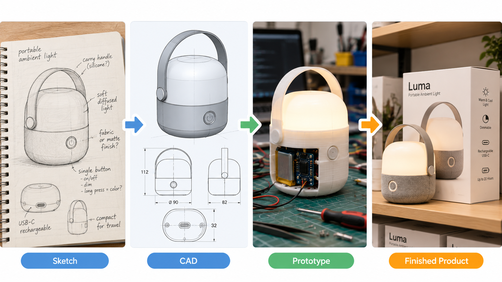
A typical development path looks something like this:
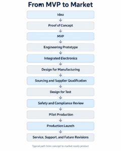
Each stage reduces uncertainty.
Each stage moves the product closer to becoming something that can be manufactured and sold reliably.
From Something That Works to Something That Can Be Sold
Getting a prototype to work is a major accomplishment.
But a successful consumer electronics product requires more than working hardware.
The electronics, enclosure, power system, software, supply chain, manufacturing process, quality controls, testing strategy, safety planning, compliance, documentation, service strategy, and business risk all need to work together.
That is the difference between an MVP and a real product.
At Jaeger Technology Group, we help customers move through that transition, from early concepts and development hardware to products that can be manufactured, tested, serviced, and prepared for market.
Have an idea that works as a prototype but needs a path to production? Jaeger Technology Group can help with engineering, electronics integration, sourcing, manufacturing, testing, and launch planning. Contact us to discuss your project.
About the Author: jaegertechgroup.com

STAY IN THE LOOP
Subscribe to our free newsletter.
Leave A Comment
Beyond ESP32 and Raspberry Pi: Designing Electronics for Real Products Development boards are one of the best tools available for product development.
Designing Products for Serviceability, Maintenance, and Field Repair A product can work perfectly on the day it is delivered and still be
From Prototype to Small-Batch Production: What Changes After the First Part Works Getting the first prototype to work is a major milestone.

Designing a Custom Interactive Kiosk: From Concept to Production One of the more interesting projects we have worked on recently at Jaeger