
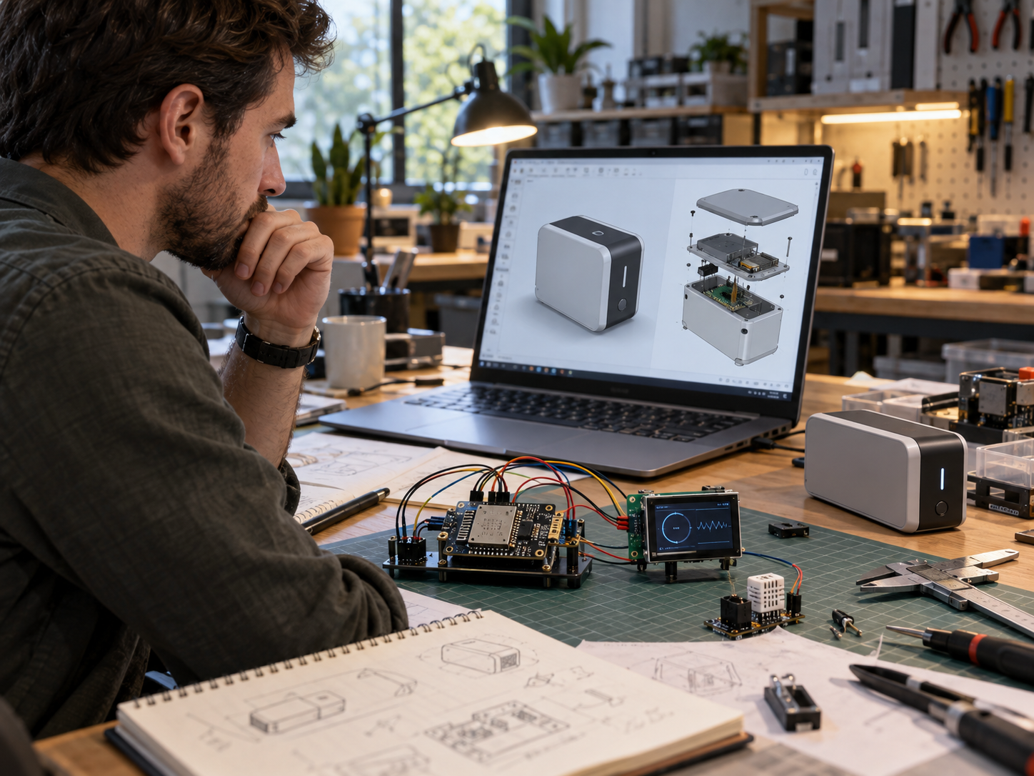
Beyond ESP32 and Raspberry Pi: Designing Electronics for Real Products
Development boards are one of the best tools available for product development.
An ESP32, Raspberry Pi, Arduino, Feather, Seeed board, or similar platform can let you go from an idea to a working prototype in hours or days instead of weeks.
That is exactly what they are for.
The problem is that a development board that is excellent for proving an idea is not always the best choice for a finished product.
At some point, the question changes from:
Can we make this work?
to:
Can we manufacture this reliably, repeatedly, and at a reasonable cost?
That is when custom electronics start to make sense.
At Jaeger Technology Group, we often look at this transition as a progression rather than a single jump.
Development Board → Custom Carrier Board → Module on Custom PCB → Fully Custom Electronics
The right stopping point depends on the product, volume, cost, regulatory requirements, and how mature the design is.
Why Development Boards Are So Useful
For an MVP or proof of concept, development boards are hard to beat.
They already provide many of the things needed to get started:
- Microcontroller or processor
- USB programming
- Voltage regulation
- Wireless connectivity
- GPIO
- Memory
- Debug interfaces
- Documentation
- Community support
- Ready-made libraries
That allows the engineering team to focus on the core function of the product rather than designing every subsystem from scratch.
A typical early prototype might look like:
ESP32 → Motor Driver → Sensor → Display → Battery → 3D-Printed Enclosure
That is completely reasonable.
In fact, trying to design a custom PCB too early can slow development and lock in decisions before the product is fully understood.
When Development Boards Are Still the Right Choice
Not every product needs a custom board.
Development hardware may remain the best option when:
- Production quantities are low
- Requirements are still changing
- Time to market matters more than unit cost
- The device has plenty of internal space
- The development board is readily available
- The current architecture is reliable
- Certification requirements are manageable
- The system may continue evolving
If you are building ten or twenty units, the engineering cost of a custom PCB may not make financial sense.
If you are building hundreds or thousands, the calculation may change dramatically.
When Off-the-Shelf Boards Start Becoming a Problem
The first sign is often packaging.
A development board may have:
- USB connectors you do not need
- Header pins you do not use
- LEDs that serve no production purpose
- Multiple regulators
- Extra memory
- Large connector spacing
- Expansion features that are irrelevant to the finished product
All of that takes up space.
The board may also force the mechanical design around its shape instead of allowing the electronics to fit the product.
At that point, the electronics begin driving the enclosure in the wrong direction.
Cost Can Become Significant
A $15 or $30 development board is inexpensive when building one prototype.
At higher volume, that cost starts to matter.
For example:
$25 Development Board × 1,000 Units = $25,000
If a custom PCB can provide the required functionality at a substantially lower per-unit cost, the upfront engineering and tooling expense may become justified.
But cost reduction is only one reason to move to custom electronics.
Often, the larger benefits are:
- Smaller size
- Cleaner wiring
- Better reliability
- Faster assembly
- Better connector placement
- Easier testing
- Better thermal management
- Improved serviceability
The Transition Does Not Have to Be All or Nothing
One of the most useful things to understand is that there are intermediate steps.
You do not have to go directly from a complete ESP32 development board to a bare microcontroller and fully custom RF design.
A more practical path is often:
Development Board
↓
Custom Carrier Board
↓
ESP32 or Similar Module on Custom PCB
↓
Bare MCU and Fully Custom Electronics
Each stage gives you more control.
Step 1: Custom Carrier Board
A carrier board can be a good middle ground.
Instead of wiring a development board to several breakout modules, the carrier board can provide:
- Power distribution
- Motor drivers
- Connectors
- Relays
- Sensors
- Protection circuitry
- Screw terminals
- Battery connections
- User-interface connections
The development board still handles processing and communications.
This approach can significantly improve assembly while keeping the core controller modular and replaceable.
For low-volume products, that may be the best long-term solution.
Step 2: Use a Module on a Custom PCB
For higher integration, the development board can be replaced with the underlying module.
For example, instead of mounting an entire ESP32 development board, a product may use an ESP32 module directly on the custom PCB.
That gives the designer much more flexibility.
The PCB can then integrate:
- Power regulation
- Motor drivers
- Battery charging
- Sensors
- Display connectors
- Buttons
- USB-C
- External communications
- Protection circuitry
This can reduce size and cost while avoiding the complexity of designing the radio section from scratch.
For many connected products, this is an excellent compromise.
Step 3: Fully Custom Microcontroller Design
At larger volumes or where space is extremely constrained, a fully custom microcontroller design may make sense.
That can mean using the MCU itself along with:
- External flash
- Oscillators
- Voltage regulation
- RF circuitry
- Antenna
- USB interface
- Programming circuit
- Protection components
This gives maximum design freedom.
It also requires much more engineering.
The PCB layout becomes more critical.
Power integrity, RF design, grounding, component placement, programming, testability, and EMC performance all become more important.
That level of customization should be justified by the product requirements.
Power Design Becomes More Important
Development boards hide a lot of complexity.
They usually provide their own voltage regulation and protection.
Once you move to custom electronics, those responsibilities become yours.
A custom board may need to manage:
Input Power → Protection → Regulation → Battery Charging → System Rails
Questions can include:
- 5V or 12V input?
- Battery powered?
- USB-C charging?
- Multiple voltage rails?
- Motor power separate from logic power?
- Overcurrent protection?
- Reverse-polarity protection?
- Undervoltage cutoff?
- Thermal protection?
- Sleep modes?
A poor power architecture can create instability that never appeared during early prototyping.
Motors, Drivers, and Higher-Current Loads Need Careful Integration
Many products include loads that a microcontroller cannot drive directly.
These may include:
- Motors
- Pumps
- Solenoids
- Relays
- Heaters
- High-power LEDs
- Speakers
The custom board needs appropriate driver circuitry.
That may include:
- MOSFETs
- H-bridges
- Dedicated motor drivers
- Flyback protection
- Current sensing
- Filtering
These loads can also create electrical noise.
Good grounding, filtering, board layout, and power separation become increasingly important as the design becomes more integrated.
ESD Protection Needs to Be Designed In
One major difference between a bench prototype and a real product is the environment.
A prototype may sit on an ESD-safe bench.
A consumer product may be touched hundreds of times per day.
Users may discharge static electricity directly into:
- USB ports
- Buttons
- Displays
- Connectors
- Metal hardware
- Sensor openings
That means ESD protection should be considered during the electronics design.
Common methods include:
- TVS diodes
- Input protection
- Filtering
- Grounding
- Connector shielding
- Appropriate PCB layout
The objective is to give electrostatic discharge a safe path that does not damage sensitive electronics.
The Enclosure Matters Too
Electronics protection does not stop at the PCB.
The enclosure is part of the ESD strategy.
Most common 3D-printing materials such as PLA, PETG, and ABS are electrical insulators.
That can be useful electrically, but it can also allow static charge to accumulate.
For some applications, it may make sense to consider:
- ESD-safe filament
- Static-dissipative materials
- Conductive coatings
- Grounded inserts
- Metal panels
- Shielding
- Grounding straps
There are 3D-printable materials specifically formulated for ESD-sensitive applications.
These can be useful for:
- Electronics housings
- Assembly fixtures
- Component trays
- Production aids
- Test fixtures
But the material must be selected carefully.
Not every carbon-filled filament is truly ESD-safe.
Resistance can vary by material, print direction, moisture, and process parameters.
A conductive-looking filament is not automatically an engineered ESD material.
ESD-Safe Enclosures Do Not Replace PCB Protection
This distinction is important.
An ESD-safe housing can reduce risk.
It does not eliminate the need for proper circuit protection.
A robust design considers:
Enclosure → Grounding → Connector Protection → PCB Layout → Component Protection
All of those layers work together.
EMI and EMC Become More Important
As electronics become more integrated, electromagnetic compatibility becomes another consideration.
A prototype may work perfectly on the bench but behave differently once installed inside an enclosure with:
- Motors
- Switching regulators
- Long cables
- Displays
- Wireless radios
- Power supplies
The system may generate interference or become sensitive to interference from other equipment.
That is where EMI and EMC considerations become important.
Potential design measures include:
- Ground planes
- Filtering
- Ferrites
- Shielding
- Cable routing
- Short signal paths
- Proper decoupling
- Controlled switching edges
These are much easier to address during PCB design than after the product fails a compliance test.
Wireless Changes the Design Again
Products using Wi-Fi, Bluetooth, or other wireless systems need additional consideration.
A development board often has a tested antenna arrangement.
A custom product may place the electronics inside:
- Plastic
- Carbon-filled material
- Metal
- Dense wiring
- Batteries
- Displays
All of these can affect antenna performance.
The antenna may need:
- A defined keep-out area
- Proper orientation
- Distance from metal
- Controlled PCB geometry
- Testing in the final enclosure
This is one reason radio modules can be attractive.
They can simplify the RF portion of the design compared with building the radio section completely from scratch.
Connector Placement Should Follow the Product
Custom electronics allow connectors to be placed where they actually belong.
Instead of designing an enclosure around the USB port on a development board, the board can be designed around the enclosure.
That can improve:
- Cable routing
- User access
- Assembly
- Serviceability
- Appearance
- Strain relief
Connectors should be placed with the mechanical design in mind.
The electronics and enclosure should be developed together.
Design for Manufacturing
A custom PCB should not only work.
It should be easy to manufacture.
That means considering:
- Component availability
- Standard package sizes
- Pick-and-place compatibility
- Board dimensions
- Assembly process
- Connector installation
- Rework access
- Inspection
- Panelization
The board should also avoid unnecessary complexity.
If a two-layer board can accomplish the job reliably, there may be no reason to use six layers.
If a common connector works, there may be no reason to specify a rare proprietary one.
Design for Testing
Production electronics also need to be testable.
That may require:
- Test points
- Programming headers
- Diagnostic LEDs
- Firmware test modes
- Current measurement points
- Fixture contacts
A production workflow may look like:
Assemble PCB → Program Firmware → Electrical Test → Functional Test → Install in Product
The easier the board is to test, the easier it is to manufacture reliably.
Programming Needs to Be Considered
A prototype may be programmed through USB.
Production quantities may need a more controlled process.
That could include:
- Programming headers
- Pogo-pin fixtures
- SWD or JTAG access
- Factory firmware
- Serial-number programming
- Configuration data
- Calibration values
The programming process should be documented and repeatable.
Component Lifecycle Matters
A consumer product may need to stay in production for years.
That means component selection should consider more than immediate availability.
Questions include:
- Is the part actively supported?
- Is it approaching end-of-life?
- Are there alternate manufacturers?
- Is it available from reputable distributors?
- Does it have a stable datasheet?
- Is there a pin-compatible replacement?
A custom board built around an obscure component can become difficult to support if that component disappears.
Compliance Should Be Considered Before the Board Is Final
Custom electronics can affect product certification.
Depending on the product, considerations may include:
- FCC
- EMC
- Electrical safety
- Battery safety
- UL or other NRTL evaluation
- Wireless certification
- Environmental requirements
Using pre-certified modules can simplify some parts of that process.
But the finished product still needs to be evaluated as a complete system.
Compliance should therefore influence component selection, layout, enclosure design, and power architecture before the design is frozen.
Custom Electronics Can Improve Serviceability
Custom does not have to mean disposable.
In fact, a well-designed PCB can improve serviceability.
For example, the product may use:
- Replaceable board modules
- Keyed connectors
- Accessible fuses
- Serviceable batteries
- Clearly labeled interfaces
- Plug-in wiring harnesses
That can make the product much easier to maintain than a prototype full of loose modules.
When Does a Custom PCB Actually Make Sense?
There is no universal production number.
The answer depends on:
- Unit volume
- Cost target
- Product size
- Assembly labor
- Reliability requirements
- Supply-chain risk
- Compliance
- Service strategy
The right question is not:
How many units before we need a custom board?
A better question is:
At what point does the custom board reduce enough cost, complexity, size, or risk to justify the engineering effort?
Sometimes that is 25 units.
Sometimes it is 250.
Sometimes it is 25,000.
And sometimes the development board should remain in the product indefinitely.
A Typical Development Path
A practical progression might look like:
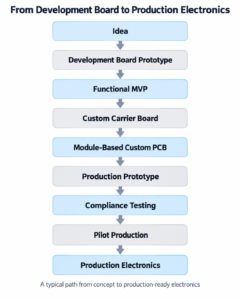
That progression allows the electronics to mature along with the product.
From Hobbyist Hardware to Product Electronics
ESP32, Raspberry Pi, Arduino, and similar platforms have changed product development dramatically.
They allow engineers, startups, researchers, and inventors to validate ideas faster and at lower cost than ever before.
They are not something to avoid.
They are often exactly where a product should begin.
The important question is knowing when the product has outgrown them.
As volume increases and the design becomes more stable, custom electronics can provide better packaging, lower cost, improved reliability, simpler assembly, stronger protection, and a clearer path toward manufacturing.
At Jaeger Technology Group, we help customers make that transition deliberately.
The goal is not to replace a development board simply because a custom PCB sounds more professional.
The goal is to choose the level of electronics integration that makes sense for the product, its production volume, and where it needs to go next.
Ready to move beyond development boards? Jaeger Technology Group can help evaluate when a custom PCB makes sense, then support the transition through electronics integration, enclosure design, sourcing, testing, and production planning. Contact us to discuss your product.
About the Author: jaegertechgroup.com

STAY IN THE LOOP
Subscribe to our free newsletter.
Leave A Comment
From MVP to Market: How Consumer Electronics Become Real Products A working MVP is an important milestone. It proves that the idea
Designing Products for Serviceability, Maintenance, and Field Repair A product can work perfectly on the day it is delivered and still be
When a Customer Has an Idea but No CAD: How Product Development Actually Starts A surprising number of product-development projects do not
From Prototype to Small-Batch Production: What Changes After the First Part Works Getting the first prototype to work is a major milestone.