

Powering and Packaging Hardware Prototypes: From Benchtop Electronics to Real-World Use
Putting Hardware Into Your Prototype: Part 4 of a Five-Part Series
In the first three articles in this series, we discussed using development boards in early hardware prototypes, choosing an appropriate controller or computing platform, and selecting sensor packages that produce useful information.
Once those decisions are made, a prototype may begin to work on the bench.
That does not necessarily mean it is ready to operate as a practical device.
A development board connected through USB power, surrounded by loose wires, temporary sensors, and exposed modules may be perfectly acceptable for proving an early concept. It can show that the software runs, the sensor responds, or the actuator moves.
However, it does not yet answer several important questions:
- How will the device be powered in actual use?
- How long must it operate?
- Where will the electronics be located?
- Will the unit be handheld, wall-mounted, installed in equipment, or used outdoors?
- Will wiring and connectors survive repeated handling?
- Will the enclosure affect sensor operation, wireless communication, or heat buildup?
- Can the prototype be tested in a way that realistically represents the intended product?
A successful hardware prototype is not simply an electronic circuit that functions on a workbench. It is a system that can be powered, packaged, handled, installed, and evaluated in a way that supports the next development decision.
A Working Breadboard Is an Important Step, Not the Finished Prototype
Early electronic development often begins with a straightforward arrangement:
- A development board
- Sensors or add-on modules
- Jumper wires
- A USB connection
- Temporary mounting
- A laptop displaying measurements or controlling the system
This is often exactly the right way to begin. Loose, accessible components are easier to replace, debug, test, and revise than electronics permanently installed in a compact enclosure.
The mistake is not using a benchtop prototype. The mistake is assuming that success on the bench automatically proves that the device will function when packaged for actual use.
Once electronics are moved into a housing, mounted to equipment, powered by batteries, exposed to movement, or used around people, new problems can appear:
- A wire disconnects during handling.
- A battery does not provide enough operating time.
- A display, radio, speaker, or motor draws more power than expected.
- A sealed enclosure retains heat.
- A sensor produces different readings after being mounted.
- Wireless range decreases when electronics are enclosed.
- A connector is difficult to access.
- A user cannot recharge, reset, or operate the device conveniently.
- An outdoor or industrial environment damages hardware that worked perfectly in the office.
Packaging and power are not decorative finishing steps. They are part of determining whether an electronic prototype can become a practical product.
Begin With the Intended Use Environment
Before choosing an enclosure or power source, the project team should define where and how the prototype is expected to operate.
A prototype intended for indoor benchtop evaluation has very different requirements from one intended to be carried by a user, mounted to a wall, installed on industrial equipment, or left outside in the weather.
Useful questions include:
- Will the device remain stationary or will it move?
- Will it be used indoors, outdoors, or in both environments?
- Will a user carry or handle it?
- Will it be attached to equipment or installed in an electrical cabinet?
- Will it encounter vibration, impact, moisture, dust, dirt, oil, cleaning chemicals, heat, or ultraviolet exposure?
- Will it be plugged in continuously or expected to operate from batteries?
- Will users need access to switches, charging ports, memory cards, displays, or replaceable sensors?
- Will technicians need to service or replace components?
- Does the enclosure need to protect users from wiring, heat, movement, or electrical connections?
These questions may reveal that the initial electronics architecture needs to change before the prototype is ready for meaningful field testing.
How Will the Prototype Be Powered?
Most development boards and sensor systems operate on low-voltage direct-current power. During early testing, that power may come from a USB cable connected to a laptop or bench supply.
As the prototype becomes more realistic, the power source becomes part of the product architecture.
Common power approaches include:
| Power Source | Typical Prototype Use | Key Considerations |
|---|---|---|
| USB cable or benchtop supply | Early electronic and sensor testing | Easy development, but may not represent actual use |
| AC/DC wall adapter | Fixed indoor devices and monitoring systems | Cable routing, connector reliability, voltage and current capacity |
| Replaceable batteries | Portable or intermittently used devices | Runtime, replacement access, battery availability |
| Rechargeable battery pack | Mobile, handheld, or field-use products | Charging, protection, battery monitoring, enclosure space |
| Dedicated DC rail | Machinery, industrial equipment, control cabinets | Regulation, electrical noise, fusing, grounding, protection |
| Vehicle or mobile-equipment power | Mobile systems and installed field devices | Voltage variation, transients, vibration, secure connections |
The power decision should be matched to what the prototype must prove.
A USB-powered electronic assembly may be adequate when the objective is to confirm that a sensor and controller work together. It is not adequate evidence that a portable, battery-powered product will operate for an entire shift or that an installed industrial device will tolerate equipment power conditions.
USB and Benchtop Power: Appropriate for Early Learning
USB power is convenient, inexpensive, and readily available. It is often ideal during the earliest stage of a prototype because it allows the developer to program the board, view sensor data, and test hardware without designing a dedicated power system.
USB or benchtop power can be appropriate when the team is answering questions such as:
- Does the development board operate correctly?
- Does the sensor provide the expected signal?
- Can the software record and display the data?
- Can a motor driver, relay, indicator, or communication module be controlled?
- Is the basic concept worth further development?
However, USB power can conceal later problems. A prototype connected to a computer may not reveal:
- The required battery size
- Charging requirements
- Real operating duration
- Cable-management issues
- Power interruptions in actual use
- Voltage fluctuations from an industrial or mobile source
- The power draw of all integrated features operating together
USB is a good development tool. It should not be confused with a complete product power strategy unless the finished device is genuinely intended to operate that way.
AC/DC Wall Adapters for Fixed Indoor Prototypes
A wall-powered design may be appropriate for devices intended to remain in one location, such as:
- Indoor monitoring equipment
- Wall-mounted sensor units
- Laboratory devices
- Displays or user-interface stations
- Desktop products
- Fixed test equipment
In these cases, an AC/DC adapter converts wall power to the low-voltage DC power needed by the development board and associated electronics.
This may be simpler than battery operation, but it still requires practical planning:
- What voltage does the system require?
- How much current is needed when all features operate simultaneously?
- Is the connector durable and difficult to disconnect accidentally?
- Will the cable create a trip, strain, or installation concern?
- Does the enclosure provide strain relief?
- Does the device need a power switch?
- Does the power adapter need to be replaceable?
- Will the intended installation have nearby power available?
- Does loss of power create any data-loss or restart concerns?
A prototype that will ultimately be mounted on a wall or installed in a facility should be tested with a realistic power supply and cable arrangement rather than remaining indefinitely tethered to a developer’s computer.
Battery-Powered Prototypes: Portability Adds Design Requirements
Battery operation is often attractive because it removes the power cord and allows the product to be handheld, mobile, wearable, field-deployed, or positioned where wall power is unavailable.
Battery power also adds substantial design questions.
The project team should consider:
- How long must the device operate between charges or battery changes?
- Will it be used continuously or intermittently?
- Can the user easily charge or replace the battery?
- How large and heavy can the battery be?
- Does the enclosure have adequate room for the battery and charging components?
- Will Wi-Fi, cellular communication, displays, indicator lighting, audio, or motors reduce runtime?
- Does the device need to report a low-battery condition?
- What happens if the battery becomes depleted during operation?
- Will the product be stored for long periods between uses?
- Does the battery need physical protection from impact, heat, puncture, or mishandling?
A battery-powered prototype should eventually be tested as a complete operating system rather than as separate components. A controller may use very little energy while the screen, radio, LEDs, speaker, pump, motor, or heated sensor determines the actual runtime.
A portable prototype that operates for twenty minutes when the intended use requires eight hours may still prove part of the concept, but it has also revealed an important product-development problem.
Power Consumption Is a System Question
Project teams sometimes focus on the power needs of the processor board while overlooking the rest of the device.
In many prototypes, the development board is not the major power consumer. Other components may dominate the power requirement:
- Displays or touchscreens
- Wireless radios
- Cellular communications
- Bright or numerous LEDs
- Speakers and audio amplifiers
- Pumps
- Motors
- Solenoids
- Valves
- Heaters
- High-rate sensors
- Cameras or edge-computing modules
A useful power estimate should account for the device’s actual operating states:
- Startup
- Idle
- Normal operation
- Wireless transmission
- Maximum load
- Charging, where applicable
- Fault or shutdown conditions
For example, a monitoring device may spend most of its time collecting low-power sensor readings but draw substantially more current when transmitting data. A motorized prototype may appear stable until the actuator reaches a difficult operating condition and draws peak current. A connected camera system may generate more heat and require more power than a simple sensor device.
Power planning should therefore happen at the system level, not only at the development-board level.
Equipment Power and Dedicated DC Rails
Some prototypes are intended to become part of a larger machine, vehicle, control cabinet, or industrial system. In those cases, the device may receive power from an existing DC supply rather than a separate wall adapter or battery.
This can be practical, but existing equipment power should not automatically be assumed to be clean, stable, or safe for prototype electronics.
Potential concerns include:
- Voltage fluctuations
- Electrical noise
- Motors or switching devices creating disturbances
- Incorrect polarity during installation
- Grounding problems
- Transient voltage events
- Excess available current during a fault
- Environmental vibration loosening connections
- Field wiring mistakes
Depending on the application, a realistic equipment-installed prototype may require:
- Proper voltage regulation
- Fusing
- Reverse-polarity protection
- Transient suppression
- Electrical isolation
- Grounding strategy
- Locking or terminal-style connectors
- Clearly labeled wiring
- Protection against accidental disconnection
A device intended for an industrial or mobile environment should eventually be tested with a power arrangement representative of that environment. Otherwise, the prototype may prove the sensor or software concept while failing to address one of the major realities of deployment.
The Enclosure Is Part of the Product Architecture
An enclosure does more than make a prototype look finished. It protects the electronics, supports the sensors, controls access to user interfaces, organizes wiring, and often determines whether the device can be handled or deployed safely.
An enclosure may need to provide:
- Secure mounting for the development board
- Mounting for sensors and accessory modules
- Battery retention
- Cable routing and strain relief
- Connector access
- Switch, button, or display placement
- Speaker or microphone openings
- Ventilation or heat dissipation
- Protection from accidental contact
- Mounting features for a wall, machine, cart, fixture, or handheld assembly
- Access for servicing, charging, programming, or replacing components
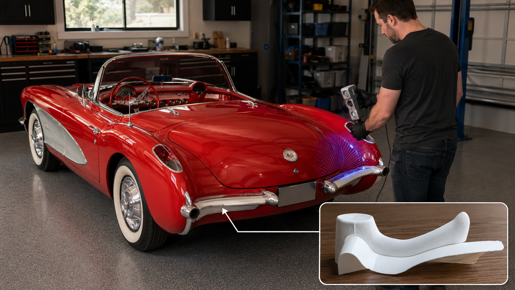
During prototype development, a 3D-printed enclosure can be particularly useful. It allows the team to revise board mounting, sensor positioning, cable openings, battery compartments, button locations, attachment features, and user-handling geometry much faster than would be practical with production tooling.
The enclosure does not need to be final to provide valuable information. A prototype housing can reveal:
- Whether the electronics fit as expected
- Whether cables can be routed cleanly
- Whether sensors can be placed in the correct location
- Whether users can operate controls comfortably
- Whether batteries are accessible
- Whether a device can be mounted securely
- Whether a display, speaker, microphone, or status light is positioned appropriately
- Whether the intended form factor is realistic
For many products, this physical integration is as important as proving that the electronics work.
Sensor Packaging Can Change Sensor Performance
Sensor placement and packaging deserve special attention because moving a sensor from a benchtop test arrangement into an enclosure can change the data it produces.
Examples include:
- A temperature sensor may measure trapped enclosure heat rather than the intended surface or environment.
- A microphone may be obstructed or affected by enclosure resonance.
- A capacitive-touch sensor may behave differently through a housing wall or overlay.
- A motion sensor may record looseness or vibration in its mounting bracket rather than movement of the product.
- A pressure or airflow sensor may produce misleading results if tubing, ports, or passages are altered.
- A wireless sensor may lose range when enclosed near metal, batteries, or equipment.
The prototype enclosure should therefore be treated as part of the sensing system, not merely as an outer shell.
When a product depends on measurement quality, the team may need to compare sensor readings before and after packaging, evaluate different mounting arrangements, and document how the sensor is positioned during testing.
Wiring and Connectors Matter Earlier Than Many Teams Expect
Loose jumper wires and temporary clip connections are useful during early electronic testing. They make it easy to swap components and troubleshoot circuits.
They are generally poor choices for prototypes that will be carried, shipped, demonstrated repeatedly, installed on equipment, or tested outside controlled bench conditions.
As the prototype matures, wiring and connectors may need to address:
- Strain relief
- Vibration resistance
- Accidental disconnection
- Polarity protection
- Cable organization
- Sensor replacement
- Battery access
- Moisture or dust exposure
- Service access
- Repeatable assembly
- Clear labeling
A prototype with unreliable wiring can waste substantial development time because intermittent electrical problems may be mistaken for software bugs, sensor faults, or design failures.
This becomes especially important when a customer, research partner, field technician, or pilot user will operate the device without the original developer standing beside it.
A prototype intended for use beyond the workbench should be packaged so that its electrical connections are appropriate to the level of testing being performed.
Packaging for Different Environments
The intended deployment environment should shape the physical prototype.
Indoor Benchtop or Laboratory Devices
A benchtop or laboratory prototype may need:
- A basic protective enclosure
- Organized wiring
- Secure sensor placement
- Accessible connectors
- Clear controls and indicators
- Repeatable positioning during tests
The key requirement may be repeatability rather than ruggedness.
Wall-Mounted or Fixed Indoor Devices
A fixed indoor device may need:
- Mounting holes or brackets
- Cable-routing provisions
- Visible indicators or screens
- Access for service or reset functions
- A suitable wall adapter or routed DC power source
- A housing that looks credible in the intended setting
The prototype should answer whether installation and daily operation are practical.
Handheld, Wearable, or Mobile Products
A mobile product may need:
- Compact packaging
- Battery retention and charging access
- Ergonomic handling
- Reduced weight
- Secure connectors
- Protection from drops and impact
- Controls accessible during movement
- Consideration of sensor readings while the unit is handled
A portable product cannot be fully evaluated while it remains connected to a laptop with loose wires.
Outdoor Prototypes
Outdoor prototypes may need to address:
- Rain or splash exposure
- Dust and debris
- Condensation
- Ultraviolet exposure
- Temperature changes
- Sealed connectors or cable entries
- Corrosion-resistant fasteners
- Battery and charging behavior in the field
- Wireless connectivity through an outdoor enclosure
An outdoor prototype does not automatically require a final production-rated enclosure during its first test, but environmental exposure should be treated as a real development constraint.
Industrial and Shop-Floor Prototypes
A product intended for an industrial setting may be exposed to:
- Vibration
- Electrical noise
- Dirt
- Dust
- Oil
- Coolant
- Impacts
- Cleaning chemicals
- Operators wearing gloves
- Maintenance practices
- Existing machine wiring and power sources
A useful industrial prototype may need terminal-style connections, protected wiring, practical mounting, clear indicators, and serviceable packaging much earlier than a consumer concept device.
Heat and Ventilation Should Not Be Ignored
Many low-power controller boards and small sensors generate very little heat. Other prototype electronics may generate enough heat to affect performance or reliability, particularly when enclosed.
Potential heat sources include:
- Linux-based single-board computers
- Edge-computing modules
- Power regulators
- Battery charging circuits
- Displays
- Audio amplifiers
- Motors or drivers
- High-power lighting
- Wireless communication modules
- Power supplies
Heat matters for several reasons:
- Electronics may become less reliable.
- Batteries may require additional care.
- Sensor readings may be distorted.
- Users may encounter uncomfortable surface temperatures.
- A sealed enclosure may trap more heat than expected.
The team should consider whether the prototype requires vents, heat sinks, thermal separation between sensors and electronics, larger enclosure volume, or temperature monitoring during realistic operation.
A prototype that only operates briefly with its enclosure open may not reveal thermal issues that appear during prolonged use.
Serviceability and User Access
A prototype intended for realistic evaluation should consider what the user or technician may need to access.
Possible access points include:
- Power switch
- Charging connection
- Replaceable battery
- Status LEDs
- Display
- Reset button
- Programming or diagnostic connection
- Sensor connector
- Memory card
- Calibration control
- Mounting hardware
Not every feature should be externally accessible. Too many exposed connections may create confusion, damage risk, contamination risk, or an unprofessional user experience.
However, sealing every component inside an enclosure can also make early testing unnecessarily difficult.
Prototype packaging should balance:
- Ease of testing
- Ease of repair
- Protection from handling
- Representative user experience
- Practical servicing
- Future product direction
The correct balance depends on the prototype phase. A laboratory test unit may need easy access to components. A pilot-use prototype may need to feel much more complete and controlled.
Testing the Prototype Beyond the Workbench
Once the electronics are packaged and powered in a realistic way, the team should evaluate more than whether the device turns on.
Useful questions include:
- Does the device operate for the required duration?
- Does the power supply or battery behave as expected?
- Does the enclosure become warm during operation?
- Do sensor readings change after installation in the housing?
- Does wireless communication remain reliable?
- Do cables remain secure during handling or movement?
- Can the device be mounted, carried, or installed as intended?
- Can a user operate it without damaging the electronics?
- Can it recover after power loss?
- Can sensors, batteries, or other service components be replaced?
- Does the prototype still accomplish the original test objective in a more realistic configuration?
This stage often reveals whether the product concept is truly practical.
A device may successfully measure a condition while being too bulky for the intended application. It may work electronically while being difficult to recharge or install. It may produce good sensor data until the sensor is moved into the required enclosure. It may function perfectly indoors but require major revision for outdoor or industrial operation.
These are not failures of prototyping. They are exactly the kinds of problems a well-planned prototype is intended to discover before full product development begins.
Keep Power and Packaging Development in Phases
As with board and sensor selection, the power and packaging process should match the maturity of the project.
Phase 1: Functional Bench Testing
At the earliest stage, use accessible electronics, temporary wiring, and convenient power sources to confirm that the fundamental concept works.
Typical goals include:
- Confirming controller operation
- Confirming sensor response
- Testing basic software
- Activating simple outputs or actuators
- Deciding whether further development is justified
Phase 2: Controlled Prototype Assembly
Move the electronics into a basic housing or fixture and use more reliable wiring and mounting.
Typical goals include:
- Confirming that components physically fit
- Establishing sensor placement
- Organizing wiring
- Testing buttons, displays, connectors, or indicators
- Beginning power-consumption evaluation
- Improving repeatability between tests
Phase 3: Representative Operating Prototype
Integrate a realistic power source, enclosure arrangement, mounting method, and user interface appropriate to the intended application.
Typical goals include:
- Evaluating battery operation or realistic fixed power
- Testing handling, mounting, installation, or mobility
- Evaluating heat, vibration, wireless performance, or environmental exposure
- Allowing a customer, researcher, operator, or pilot user to evaluate the device
- Identifying remaining product-development risks
Phase 4: Planning for Product Integration
Once the prototype architecture has been tested, begin evaluating production-oriented requirements.
These may include:
- Dedicated electronic assemblies
- Production enclosure materials and processes
- Final battery or power architecture
- Connector and cable specifications
- Environmental protection
- Manufacturing repeatability
- Service strategy
- Compliance and testing requirements
- Product documentation
This approach allows the team to learn in manageable stages rather than attempting to design the complete finished product before basic feasibility has been proven.
A Practical Prototype Must Work Where It Will Be Used
A hardware prototype becomes far more valuable when it moves beyond a successful benchtop demonstration and begins answering real deployment questions.
The controller may function. The sensors may measure. The software may collect useful information.
But the device must also be able to operate in a practical physical form.
That means asking:
- How will it be powered?
- How long must it run?
- What other components determine the real power requirement?
- Where will it be located?
- What will it be exposed to?
- How will electronics, sensors, batteries, and cables be mounted?
- Will the enclosure interfere with measurement, communications, or heat dissipation?
- Can users or technicians operate and service it appropriately?
- Can it survive the level of handling required for meaningful testing?
- Does this packaging approach provide a reasonable path toward a finished product?
A good prototype does not need to solve every production problem in its first revision. It should, however, expose the right problems in the right order.
A benchtop circuit demonstrates that an electronic idea may work. A powered and packaged prototype begins to demonstrate whether that idea can become a real product.
JaegerTech Can Help Turn Electronic Concepts Into Practical Prototypes
At Jaeger Technology Group, we help customers move hardware ideas from early functional concepts toward testable, practical prototypes.
That process may include:
- Development-board and sensor integration
- Electronic packaging
- 3D-printed prototype enclosures
- Sensor brackets and mounting fixtures
- Battery and power-source planning
- Cable routing and connector access
- Wall-mounted, handheld, benchtop, industrial, or field-use prototype housings
- Test fixtures and evaluation assemblies
- Planning for later production-oriented product development
Whether a project needs a simple benchtop proof of concept or a more representative electronic product prototype, the goal is the same:
Build something that works, package it in a way that can be meaningfully tested, and make the next development decision with greater confidence.
About the Author: jaegertechgroup.com
STAY IN THE LOOP
Subscribe to our free newsletter.
Leave A Comment
Best $150 I’ve Ever Spent on This Car Classic car projects have a way of turning simple problems into complicated ones. A

Why Domestic Tooling and Prototype Fabrication Still Matter Low-cost overseas tooling can be tempting. When a quote comes in dramatically cheaper than
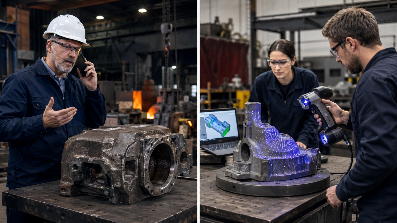
When the Pattern Is Gone: 3D Scanning a 55-Year-Old Casting for Foundry and Machine Shop Review A foundry partner recently called us
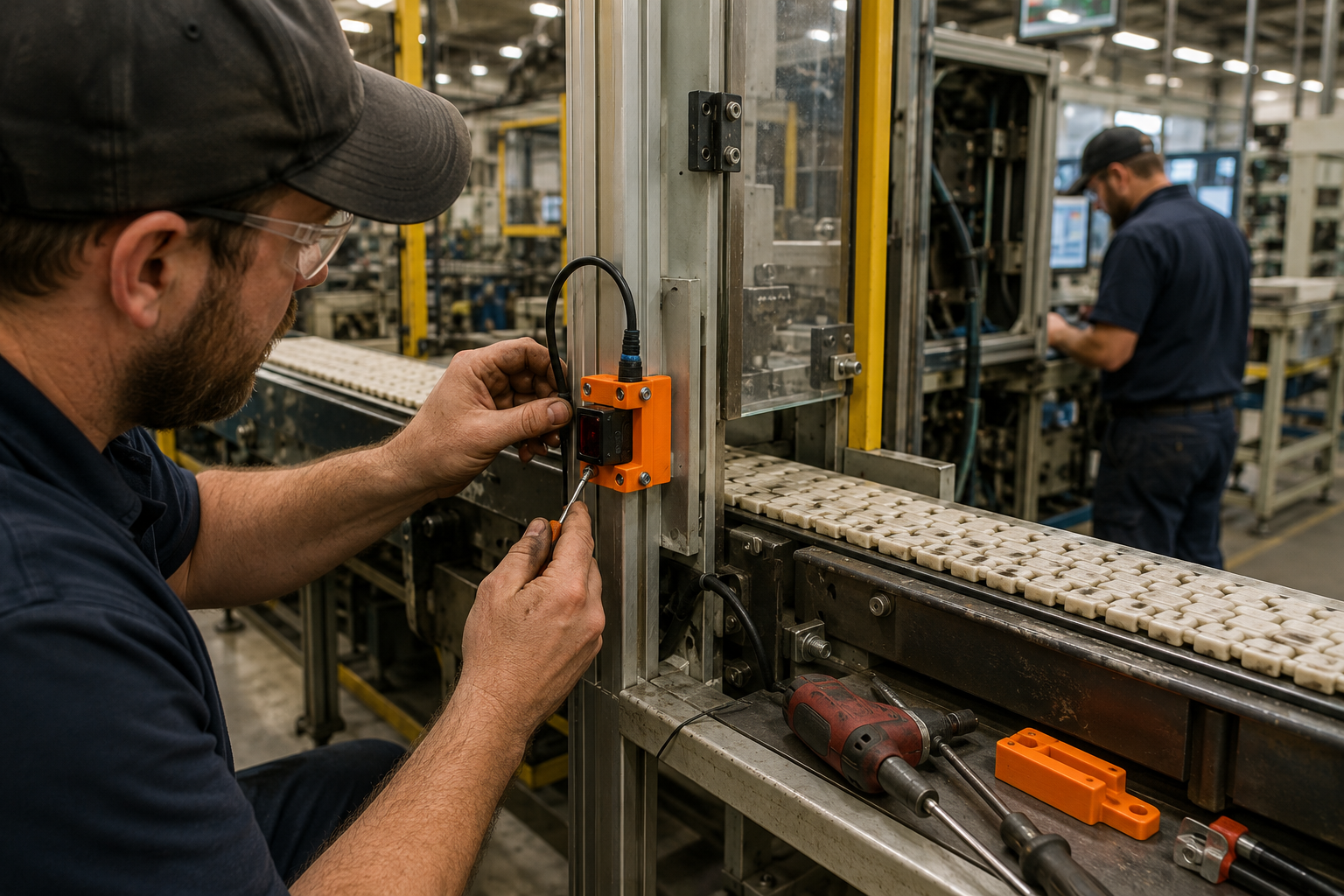
Four Hours From Problem to Part Emergency 3D Printing for Manufacturing Downtime When a production line is down, the clock starts immediately.